LC Racing Lancia Delta Integrale.
(LC-PTG2-HK)
31/8/22

Hello fellow RC car enthusiasts and thank you for joining me. I hope you are all well.
In this post, I will be taking us through the small list of assembly requirements needed to use the roller version PTG-2-HK, 4WD rally car. This version is becoming increasingly difficult to find (and very expensive), so I have just ordered the last one in stock from a UK supplier. It should be here be the 31/8/22. It cost £199, it has no shell (£56.88), electronics or motor.
The shell apparently is supplied by Hot Bodies, if I am correct. I had always promised myself a Tamiya version of this car but when LCR released this car, I erased the Tamiya version from my mind. My reasoning being, is that this car has been properly engineered and the reviews I have read are more than promising. I am certainly not throwing disrespect at both the Tamiya versions. They are also two, awesome model kits.

The bodyshell is indeed a Hot Bodies pre-painted, decaled and has light buckets pre fitted. The part number is KB48248. As I had previously stated, the body that I quoted being £70.91 was fitted with a lighting kit. As this will only (at the moment) be a display car, the full light kit will be a waste. I will only fit the LED's to the headlights and tail lights. With that being the case, I have secured the correct shell for (without LED's but has the light buckets) for the car at £56.10 including delivery. The body shell should be delivered (as stated by the seller), here on Thursday 1/9/22.

Whilst I was buying parts, there was one (well 4) thing I needed to finish the rally scale look, a set of mud flaps.

Luckily LC Racing have a wheel arch liner and mud flap kit. The part number for the arch liner and mud flaps in LC8038 and cost me £19.50 including delivery. As you can see from the picture above, the mud flaps are removeable and changeable for different colours. In my humble opinion, all off road cars should have the option to have these kits available or be included in the kit, like the new Tamiya Astute RC kit.
There is one part that still eludes me, so I am off to try and find it.

It is finally here fellow enthusiasts. A picture of the front of the box.
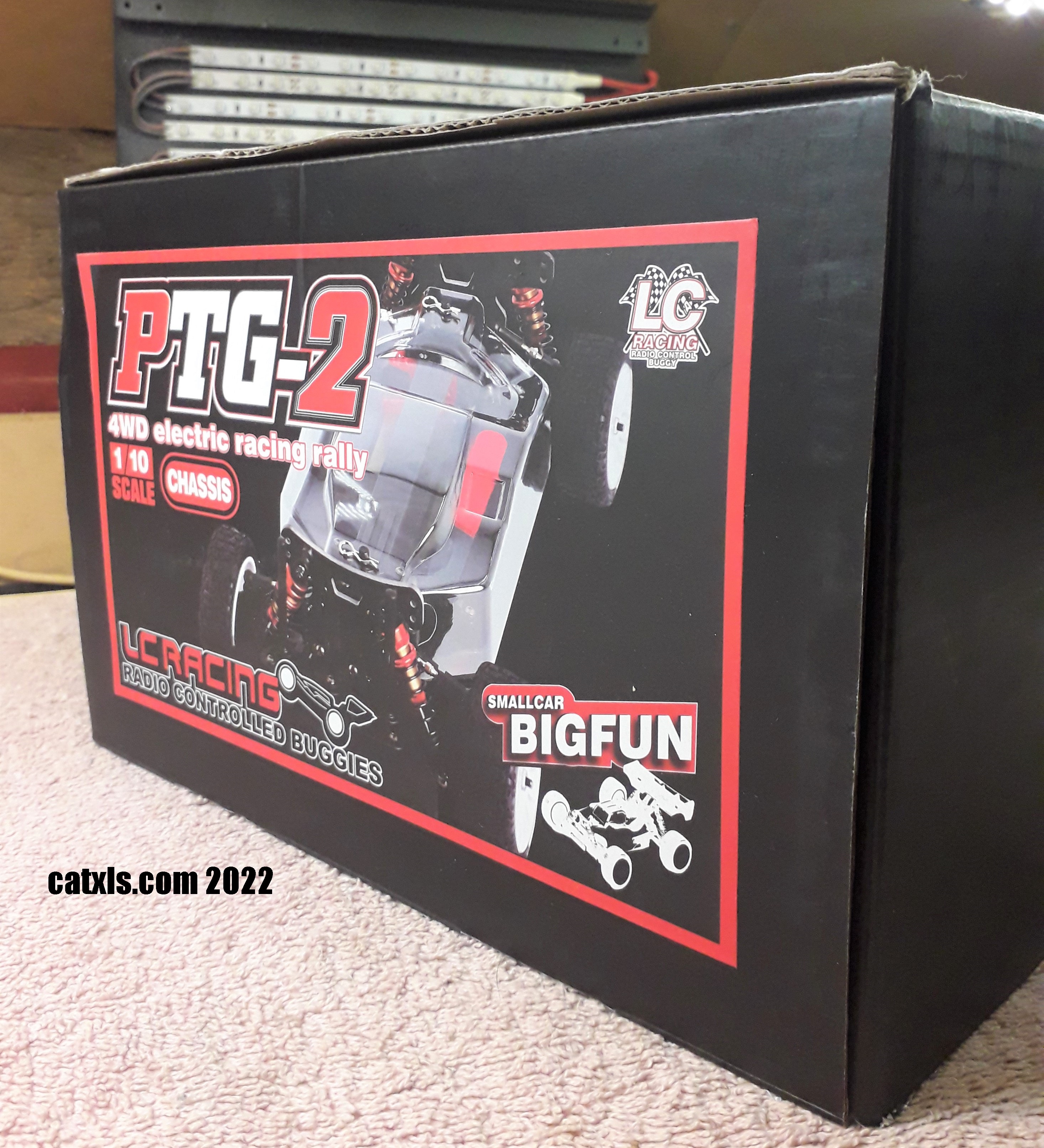
A picture of the left side of the box. Time to open the box.

Believe it or not, (apart from 2 empty cardboard boxes) this is all that is in the box. There are no instructions or build manual in the box. The smaller bag in the picture contains body clips, a pinion and some body holders.

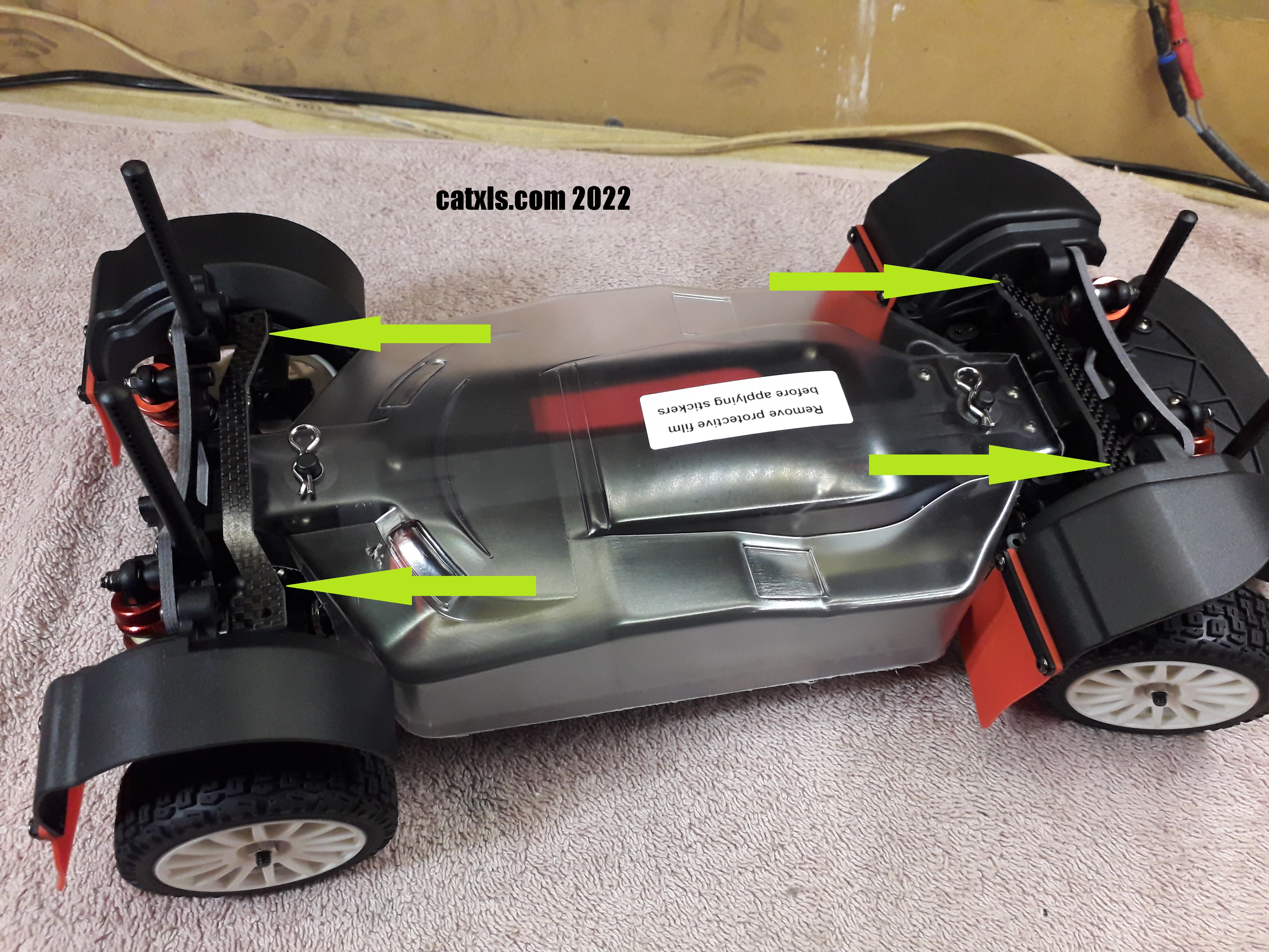
With the protective bag removed, I was relieved to find a polycarbonate chassis cover (indicated by the blue arrow) as this was the part I was referring to earlier. I stated that It "eluded" me as I was led to believe it was not supplied in the kit! Happy days. The cover can be painted with a TS Tamiya paint but for now, it will stay transparent.

An underbody picture showing the aluminium chassis plate. I wonder if there are any chassis skins (stick on covers) available for this car as they are available for other RC chassis.

As the yellow arrow points out, the car is fitted with rally/off road tyres and are fitted to 50mm (2") wheels. The wheels fitment is the standard 12mm hex fitting. The tyres are pre glued and have quite a low profile. The compound feels very soft, she should grip well on a variety of driving surfaces and different weather conditions.

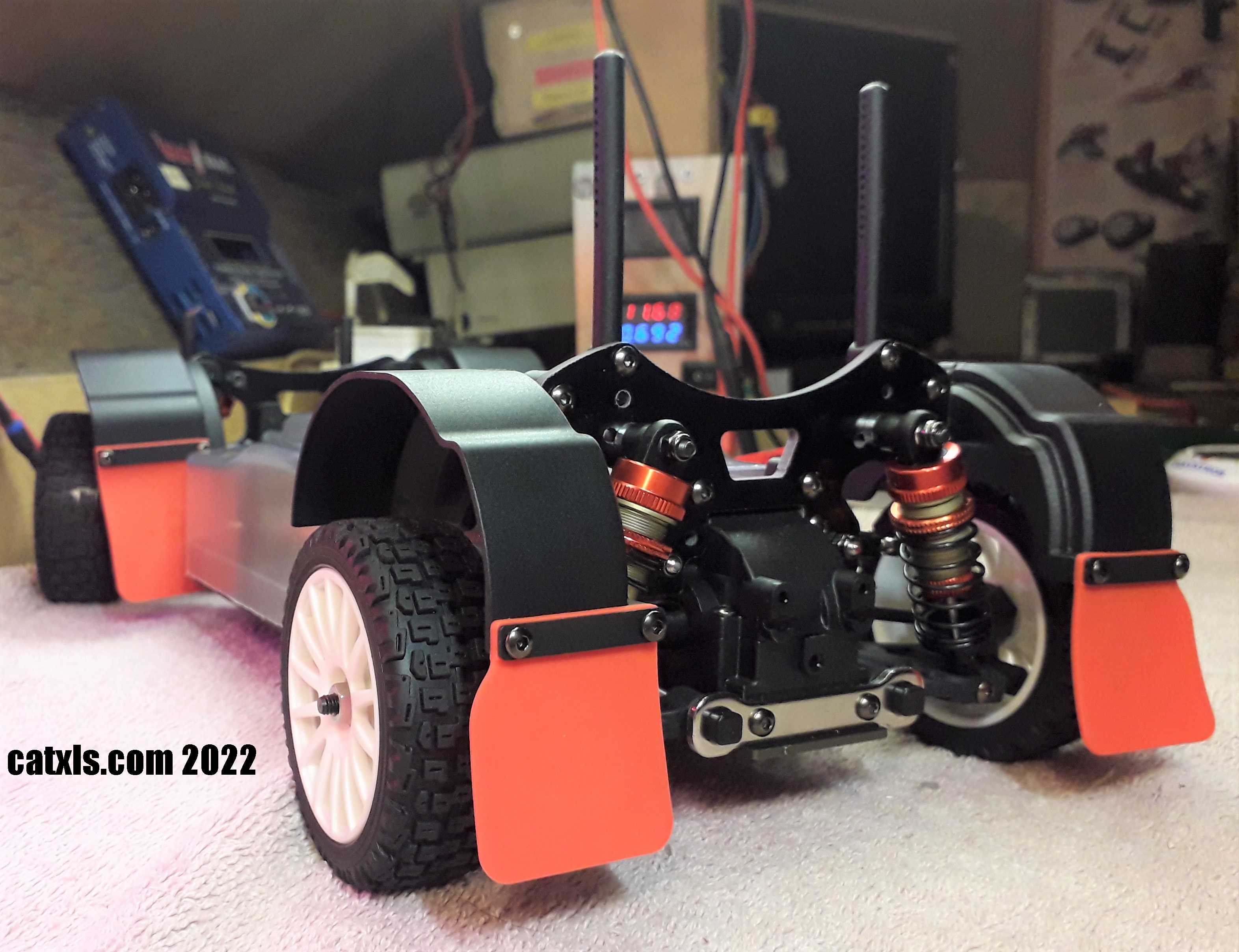
The yellow arrows above are pointing to the front and rear adjustable turnbuckles, giving the driver the opportunity to change the camber on all four wheels. Adjustable turnbuckles are normally fitted to higher end racing cars and buggies as we have here. To be fair, for the price, they should be fitted.

The pink arrows above are pointing to the FRP shock towers. Again, only higher end RC cars are fitted with this material. They will be very strong and stiff and can take some abuse but I can see me changing the towers for carbon fibre in the near future.

The yellow arrows above are pointing to those beautiful big bore adjustable shocks finished in red and grey. I must say, they are very, very smooth and dampen the car perfectly. The shocks also have an impressive 10mm of travel. I know you'll say that's not a lot, but remember this is a car and not a buggy. The shocks will also give excellent handling and yet provide a very forgiving ride for the car.

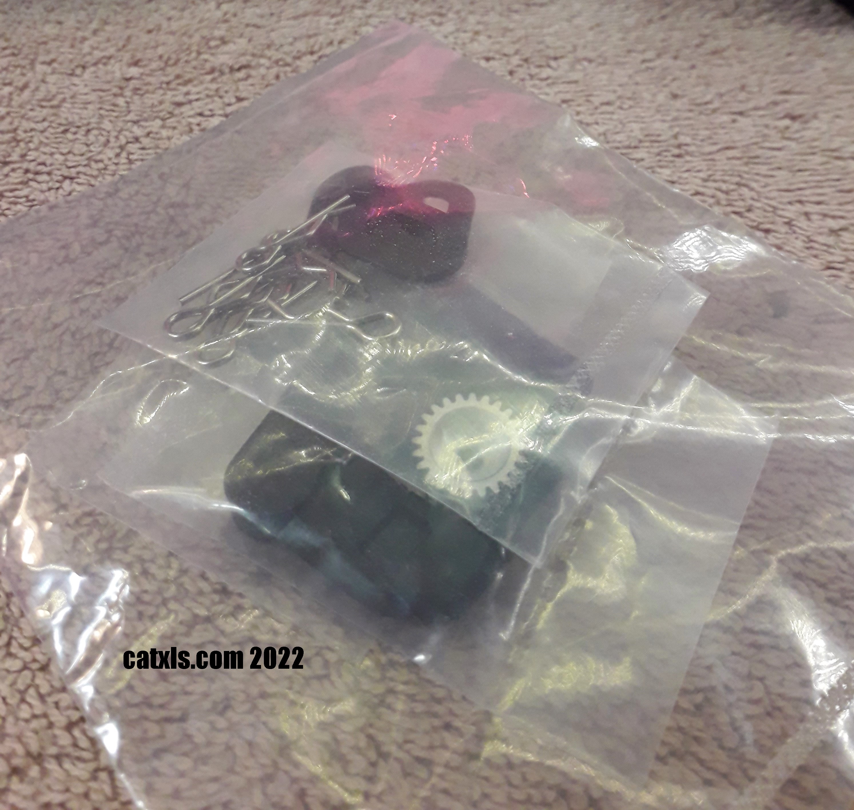
The picture above is a small bag that contains body clips, body mounts and a pinion gear. As I stated earlier, no tools, oils or even a build guide/manual are included, which I find strange.
I know I have stated the car should be supplied with this, that and the other for the price. But, being honest I know this car is worth every penny. The nearest car I can compare it with, is the Tamiya XV-01 Lancia Delta which is more expensive but does come with a body shell. This particular kit does not come with a body shell. Therefore, it is quite a difficult car to compare with another. There is a kit available for the PTG2, that comes with everything but it costs a lot more than the Tamiya XV-01. The Tamiya (I believe), is supplied with a standard silver can 540 type motor, whereas the PTG-2 doe's not. Anyway, I am extremely happy with the car and that's the most important thing to me.

The arch liners and mud flap kit (LC8038) arrived this morning (1/9/22). Again, that kit did not come with any fitting instructions.

After opening the bag, I was pleasingly shocked by the quality of the parts and the build quality. The plastic is very think and red mud flaps are very flexible so they will stand up to some punishment and the test of time. I think they look and feel awesome. As you can see the kit does come with the hex bolts to secure them into place.

After figuring out how the kit attached, I quickly threaded the plastic holes on the arches before fitting them. This makes it much easier to fit them and easier to line up as they are a tight fit. Personally, I think it looks awesome and I am very happy with the result.

A picture the of wheel liners and mud flaps from the rear. Yes, it was expensive, but I do so love it. It's maybe (maybe) my favourite car in my small and humble collection.

If you look at the right rear wheel liner you can see it is not lined up correctly. This is because I didn't realise there are other parts required namely, front and rear carbon fibre braces. The brace parts number is LC8046 and cost £15.99 including delivery. These parts will straighten the mud flaps and wheel arch liners.
As you can see from the picture above, the front left wheel arch cover is also misaligned and again there is a brace to fit to the front wheel arch liners.


At last (24hrs hours later), the braces have arrived (2/9/22). Again, there are no instruction so I downloaded the official manual and it was useless for finding how the braces were fitted as it wasn't included in the manual. It got worse, not only did I not know how to fit them, there was nothing supplied to fit them with (no hex bolts).
It wasn't difficult to work out where and how they were fitted. The mounting positions are arrowed above.

After finding some "like for like" bolts, I first fitted the front wheel arch brace as can be seen above. The orientation of the brace can be the only logical position it can be.

I then fastened the rear wheel arch cover brace into position, indicated by the green arrows. The blue arrows are indicating a major, future MISTAKE. I will get to that later in the post. DOH.

This was also delivered today (2/9/22).

As you can see, it is a Killerbody 1/10th scale Lancia Delta Integrale.

As you can see, it is fully painted and decaled. There are some other parts I have yet to fit and are in the bag to the right of the shell. It was quite expensive (£56.88 inc. delivery), but under close inspection it's worth every penny.

I love that roof air intake!

The detail on this thing is amazing. The BEST I have ever seen. It truly is spectacular and again I will say, worth every penny. Excellent quality too.

A look at the inside of the shell shows the silver backing paint.

At the front of the body shell, the pink arrows are pointing at the head light cluster bowls, which are ready for LED's to be fitted!!
And the rear light cluster LED bowls, again ready for an LED kit.

In my excitement, I quickly fitted the rear wing as can be seen above. All I had to do now was fit the wing mirrors, and then I realised there were no holes for the mirrors. I didn't want, or expected to drill holes in my new shell. I thought to myself, well it's only two holes and were readily marked so it wasn't that bad of a job. Then, I realised there were no pre drilled body post holes. At this point I was very disappointed, but it wasn't the end of the world. After all, over the years I have successfully drilled and cut numerous body shells and wings, what could go wrong?
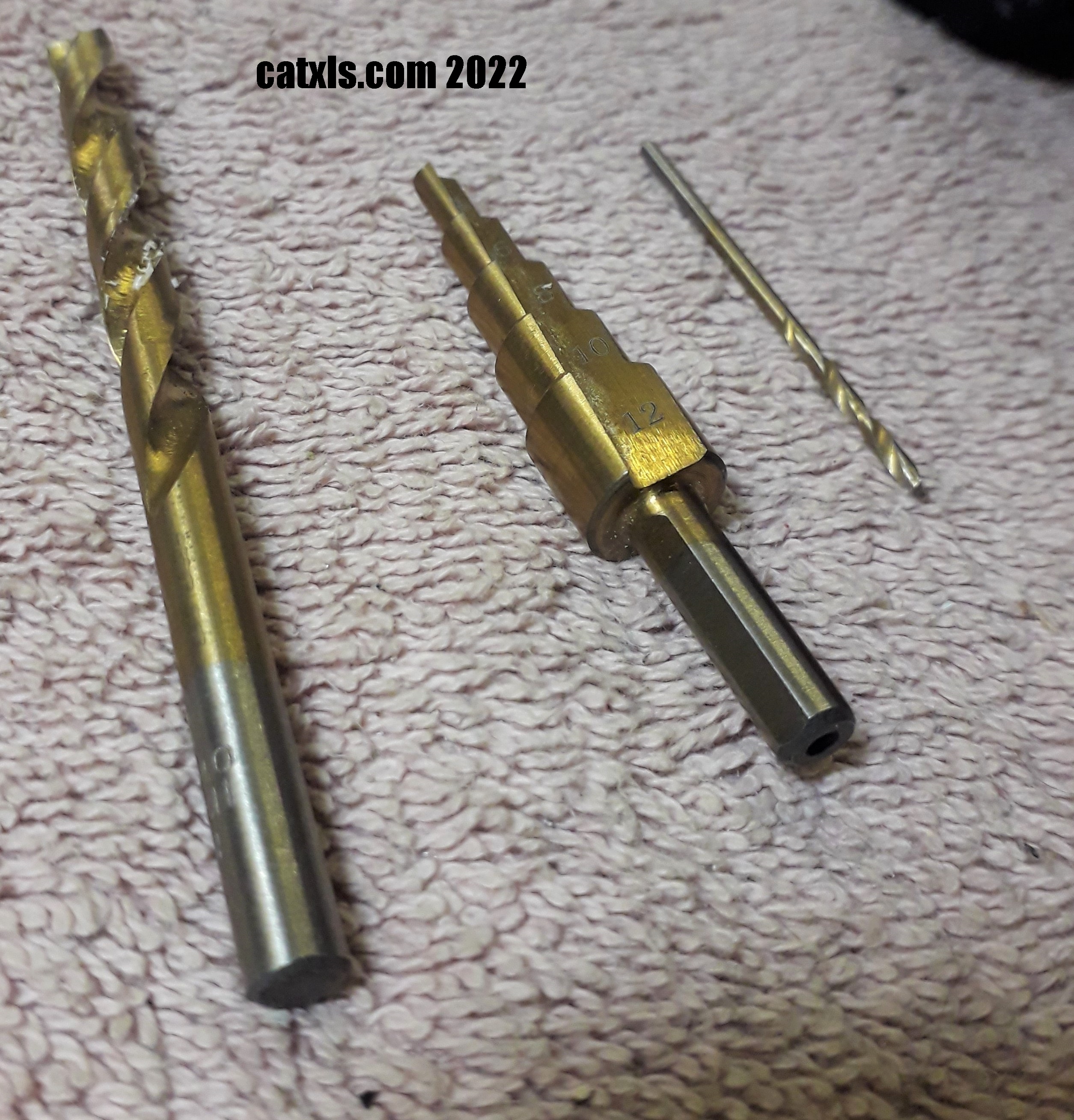
Above is a picture of the bits I will be using for the drilling operation. From left to right, 6mm hss bit, then a 12mm stepping bit and a 2mm hss drill bits. Before starting the job, I checked the drill bits were super sharp and they are. I use the 2mm bit to make a pilot hole, then I use the 6mm bit to get near the size and then finish to size with the stepper bit. This method has proven to leave great results and super round holes with little to no burring! With this shell costing a bit of money, I wanted to get it correct on the first attempt.

After I took this picture, I looked at it and noticed a massive problem. The rear wing would no longer fit in it's current position. However, the wing could not be repositioned, it had to stay there where it is supposed to be. The problem was, I had placed the body posts on the wrong side of the shock mount plate and therefore the holes were in the wrong position.

The blue arrows above, show where I had wrongly fitted the body posts to the front of the rear shock tower.

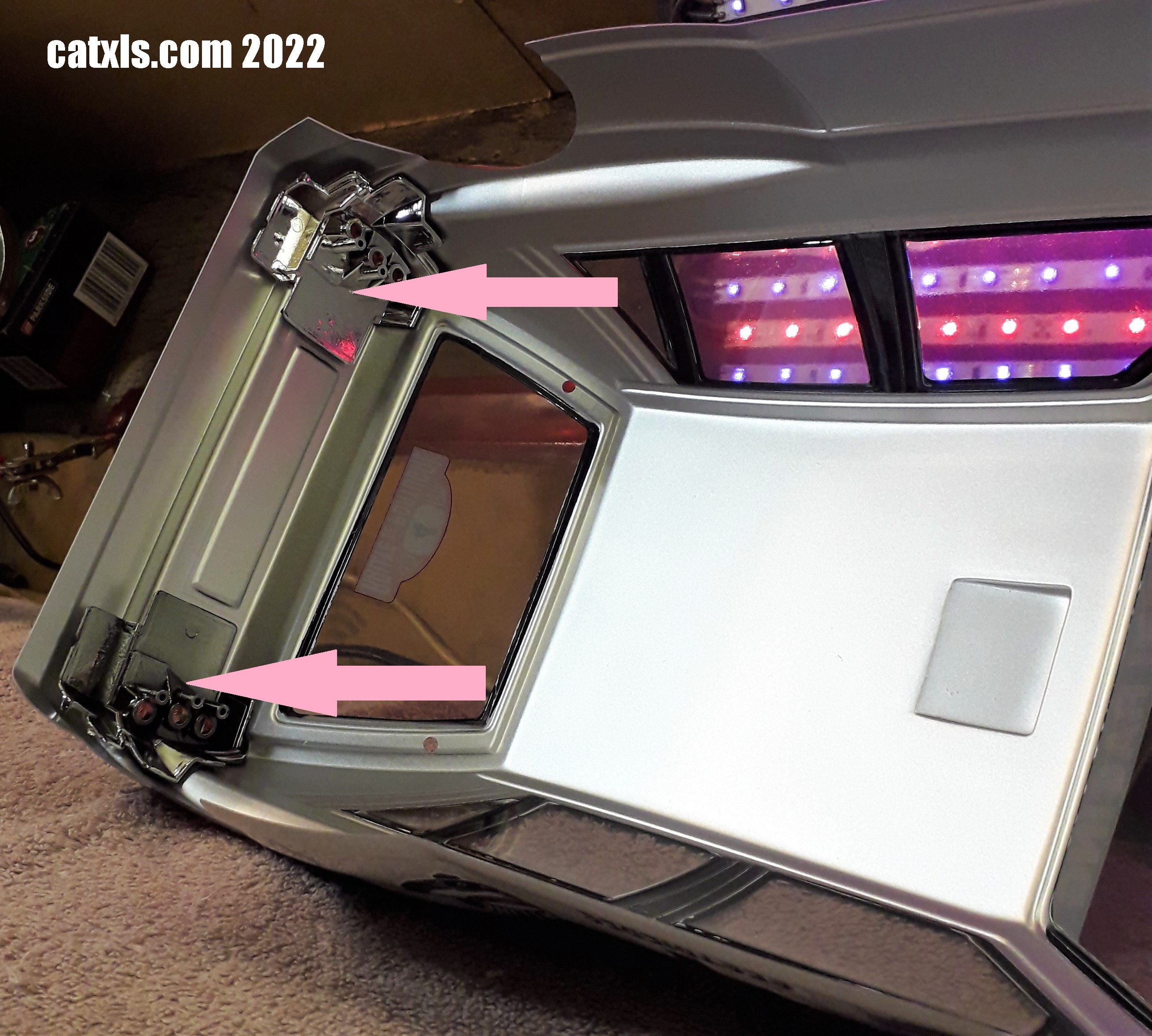
After the the realisation (and lot's of sobbing), I moved the body posts to their correct position as can be seen above (pink arrows). It was time to cut some(more) new holes.

With the body posts in the correct position, I reluctantly drilled new holes as can be seen in the picture above. At this point, I also decided to hide the wrongly drilled holes with a couple of decals. It's not the end of the world (small sobs).

With the new positions drilled, the rear wing in place it's difficult to see the wrongly drilled holes but, I will still cover them with decals.

Another picture of the extra un-needed holes.

With the rear body posts correctly positioned at the rear of the car, it was time to drill the front body post holes.

The front body post holes were easy to position and drill as can be seen above.

After drilling both the front and read body post holes, I went to drill the holes for the mirrors and I was gladly shocked as the holes were in fact, pre drilled.

I am personally loving this car from every angle.

Wow. I will, in a later update be fitting some wider rear 12mm hex drives to bring the rear wheels out a little further into the wheel arches.

I do have many further ideas and plans for this great car, so please stay tuned for further updates.
Until then, please take care my fellow RC enthusiasts and, have a look at this running video from Tomley RC (Phil's) wicked fast LC Racing PTG-2 in action here.

As you can see from the picture above, I have bought some new wheels and tyres to personalise it. During my search for these wheels, I found that the choices of tyres quite limited as was the choice of wheels. However, these wheels are the correct period and used on many rally cars of that era. Correct me if I'm wrong but, I believe these wheels were originally designed by BMW to use on their rally cars.

The wheels are the world rally acclaimed Fifteen52 Turbomac rims for my RC car and made by hpi-racing. They cost £21.54 for fours wheels.

The wheels come with a cover that clips over the top just like the real wheels but can be used without them. If I decide to use the car, I would use the covers as they will stop stones getting into the wheels. The kit also comes with a pack of decals that can be applied to the wheel covers, which is cool.

The tyres I choose are not very good to be honest and way too soft. They are JC Racing Product T6 road tyres with foams. I chose the JC Racing tyres as they have normally been excellent judging from past experiences. They were only £12 for the four so I am not too bothered. I may change them in the future.

As I am undecided about the tyres, I have not fitted the foam inserts or glued the tyres to the rims. Time to see what the look like on the car.

Humbly I say, wow, I love it and it gives the car a more aggressive stance.

I should have chosen a tyre with a larger profile as these low profile tyres look a little lost on these wheels but they will do for now.

A lower view of the rear of the car.

A picture of the wheels minus the covers. I quite like them like this too.

The tyres look a little better at the front but still look a little lost. Although I may not be 100% happy with the tyres, I am 110% happy with the look of the wheels.

I would imagine the wheels might be bit of a marmite situation for some. I personally love them and but some people may think they look ugly. They say "beauty is in the eye of the beholder" and that is certainly true here.
I know I hadn't planned to run this car, but my curiosity is so that, it's an itch I have to scratch. It also won't cost me anything as I have everything needed to try it out. Non of the equipment I am using is state of the art as it will be too fast for me as I will be trying it indoors. Last time I did that with my standard Cat XLS and broke a plastic ball joint. I'll also wait until the wife is out, as she will go crazy with me. Ok, let's have a look at the equipment I will be installing.

I'll first be installing a steering servo. The servo I am using is an Alturn AAS-750MG high torque servo, simply because I have it spare. It is a few years old but it has only been used once or twice.

The servo is mounted to two different size brackets, the right one has the yellow arrow while the left has a green arrow. One the brackets are fitted to the servo, the brackets are then bolted from underneath with counter sunk head hex bolts.
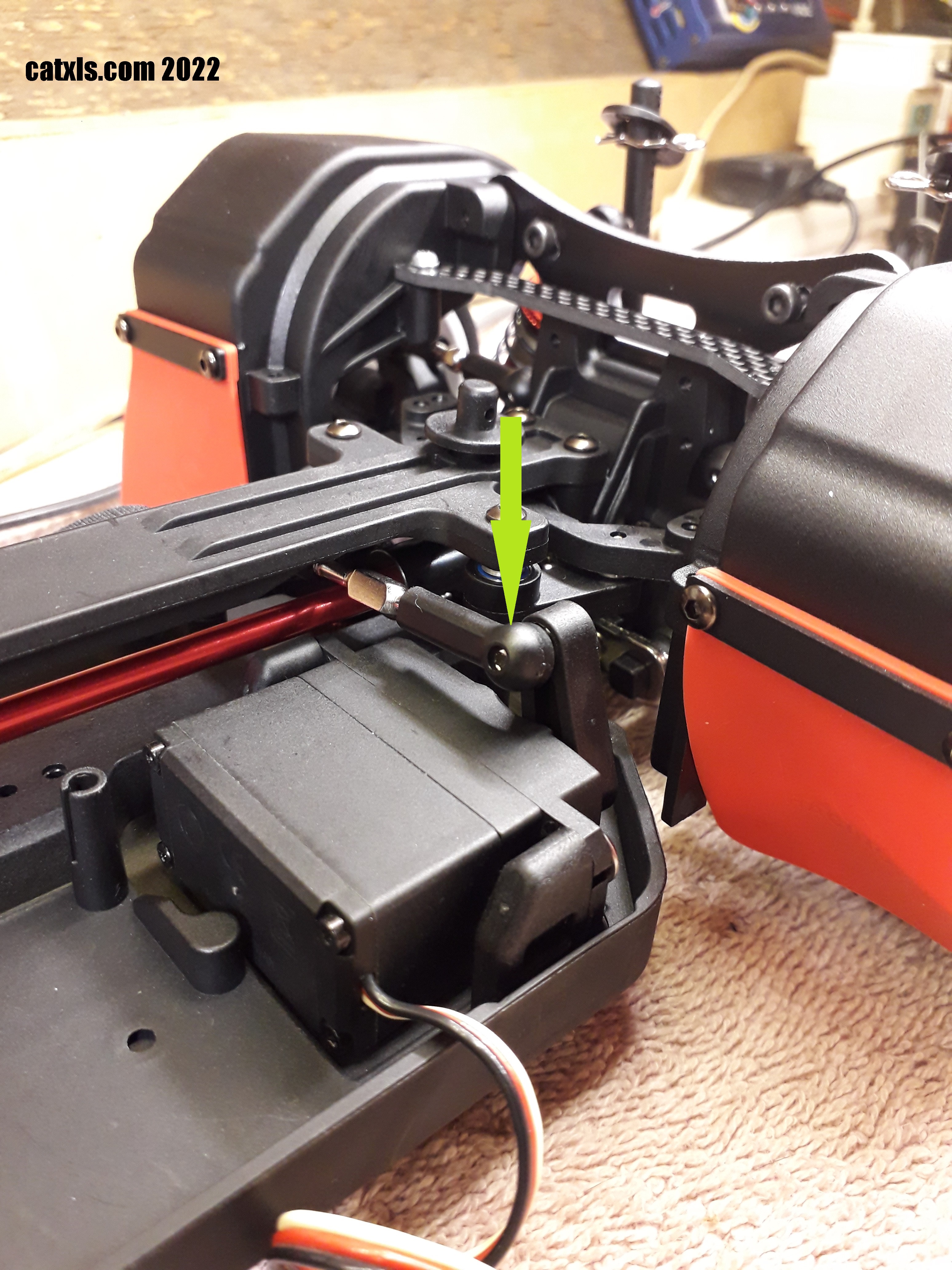
In the picture above, you can see the ball joint is fitted to the bottom of the servo arm.
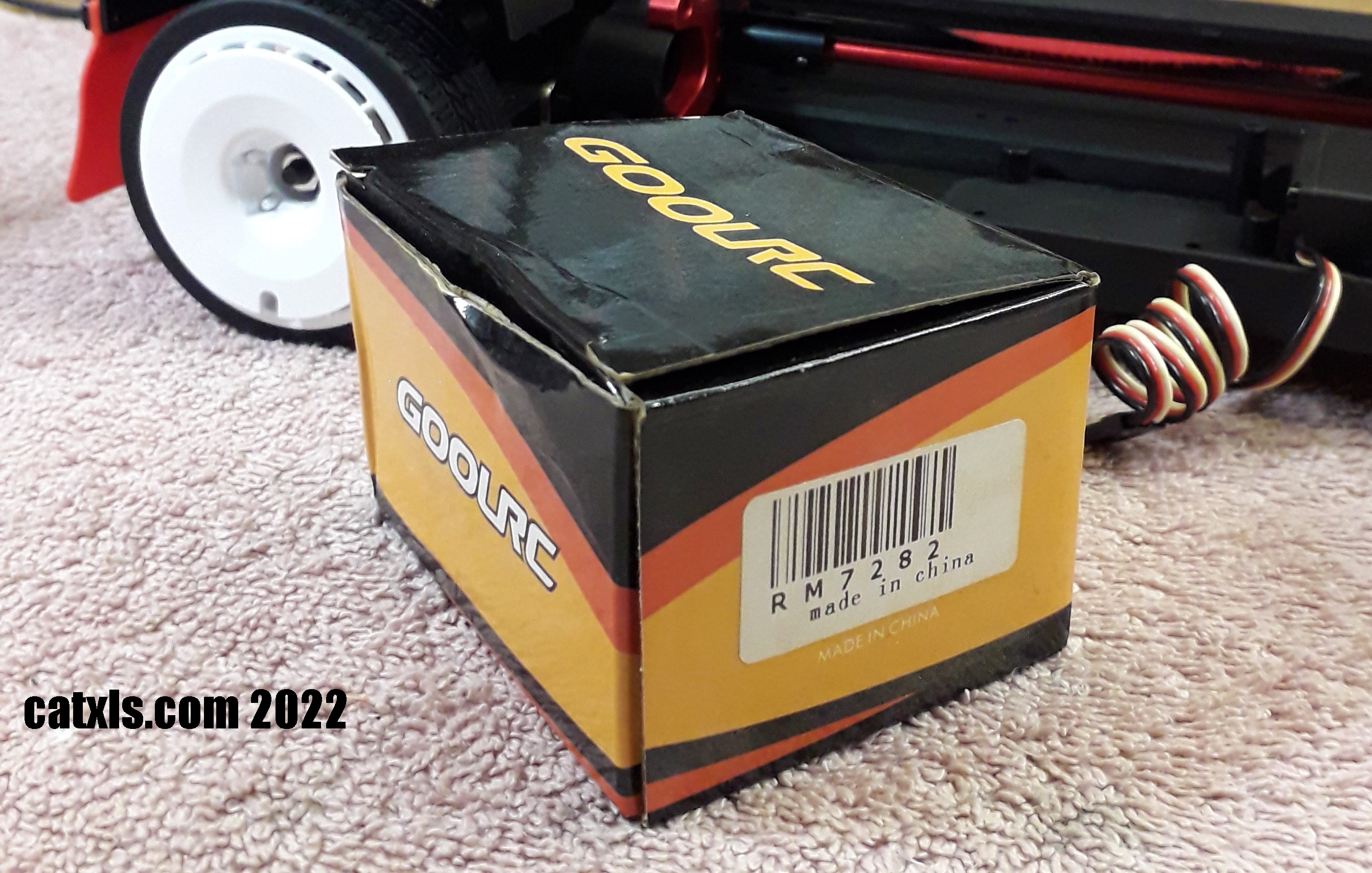
Again, I am using a motor that I already have and also has seen little use. It is a GoolRC 13 turn brushed motor that should be quite fast.

I will be very honest, fitting that motor was not an easy task but at least it's over now (so I thought).

As you can see the motor hasn't seen a lot of use and should be perfect for this car. I do have a slower motor but I know this car can handle this motor. I say this as I have seen other owners using powerful brushless motors and with up to a 3S battery. I plan on using a NiMH battery in this car when I run it. That should calm it down a lot.

For the electronic speed controller, I am using a Hobby Wing 1060 Brushed system. This ESC is brilliant. It can handle up to 12 turn motor and can use either LiPo or NiMH type batteries. It also boasts of being waterproof but I have not intention of getting the car or the ESC wet.

The above picture shows how to select a battery type by changing over a jumper pin link.

The picture above shows the position and orientation that the ESC will fitted with some double sided sticky foam.

As this is a one off test run, I will not be tidying up the cable runs. As long as they are not fouling anything, they will be ok.

On the other side of the car, is the battery strap holding the NiMH securely in place. It is a 3300mAh pack. Just to the left of the battery, is a small 2.4GHz, 3 channel receiver held in place with double sided sticky foam. With everything now installed, it's time for the first test.
As you can see it was awesome for about 10 seconds, then disaster struck. The set screw fastening the pinion to the motor shaft came loose...DOH!! Time to remove that motor mounted in an awful place as you will see.

To remove the motor, first remove the rear right wheel.

Then remove the lower pivot point bracket.

And the rear right shock assembly, bottom arm, upper suspension arm and the rear right drive shaft. I can finally get (just) to the motor securing bolts.

The orange arrows in the above picture point to the lower hex bolt holding the motor in place, hence why I removed everything in that area. This is by far the worst of the two motor mount bolts to insert or remove.

The green arrow is pointing to the out of focus upper motor mount bolt, which is a lot easier to access than the lower bolt.

The above picture shows the car almost rebuilt after refitting the pinion cog and tightening it as hard as possible. I don't like to use thread lock on such small hex bolts and I also try to avoid using it in a gearbox if I can, for the obvious reasons.
I do apologise for the shaking of the camera guys. I'm trying to do everything with one hand. However, as you can see it all works perfectly. Happy days!
Although the car is now laden full of the electronics required for operation, the small video above shows how good those shockers really are.

Well Guys,
as soon as the wife goes out, I will be updating this post so please stay tuned.
Until then, take care fellow RC enthusiasts.
Thank you for reading my humble blog.
24/9/22
catxls.com 2022
Comments