As you can see the three, 100 watt resistors bolted and thermally pasted to the heat sink. I later moved the resistors into new positions for better heat dissipation. I have the resistors connected in parallel, each with a switch. Therefore resistor 1 = 8 ohm, with resistor 2 in parallel = 4 ohm and finally resistor 3 in parallel = 2.66 ohm. In hindsight I could have used a small value resistors as I will only be discharging up to 3S maximum. This would have sped up the discharge process.
I also needed a temperature measuring device on top of a voltmeter, ammeter and watt meter so I built an all in one device that you can see above. It is a very handy little instrument indeed. I can now free up my multi meter to employ elsewhere.

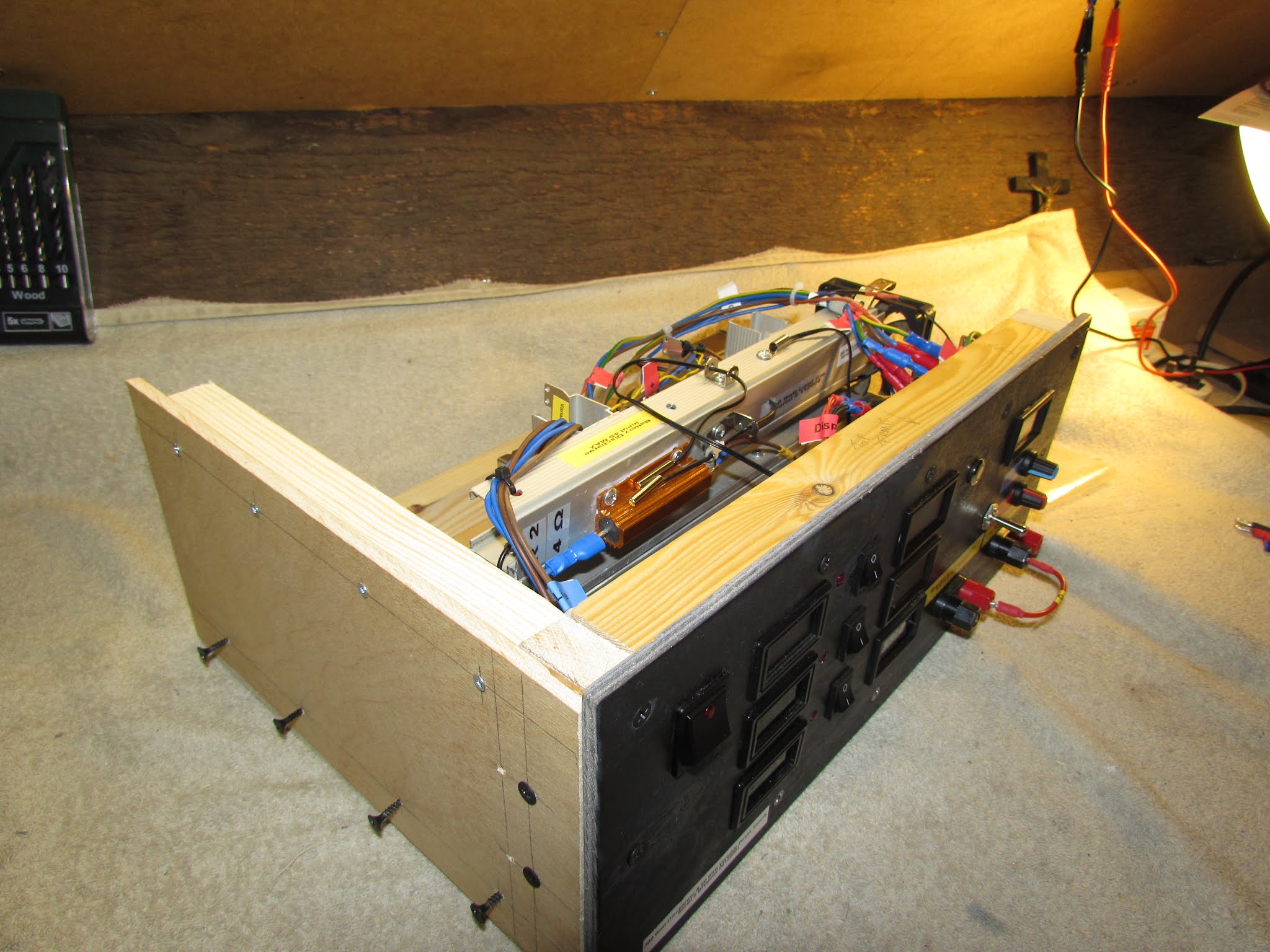
With the heat sink and resistors assembled, this gave me the rough dimensions of my front panel as can be seen above. It is made from reclaimed 6mm marine plywood, which is also fire retardant. You may also notice some of the parts are dusty and some of the cables are different. This is due to the fact that around 50% of the components I used here are reclaimed from various items. I am recycling and repurposing them as I don't like waste or needless spending. After saying that, this build was not cheap and another reason for you not to copy my design. There are now a number of high current dischargers on the market at the fraction of the cost of this unit without the hassles of designing and building it. The design, build and tests cost 3 months of all my spare time, what with design changes or unforeseen circumstances.
As you can see, there will be 6 displays on the front panel. There is also 2 sets of binding posts, a toggle switch and a mains switch (not shown). The first row of displays on the left will all be temperature monitors for each resistor. Then next 3 displays will be a timer at the top, then a temperature controller and the bottom one will monitor the voltage, current, discharge capacity and power of the discharging battery. There will also be another display at the top right as I am also installing a variable DC power supply.
The picture above shows the displays in place with their corresponding resistor switch to the right. There will also be an LED on each switch as a quick glance reference.
I have populated the front panel with components to check the fit. The above displays are for demonstration purposes only and will change. I have also installed the control potentiometers for the variable DC power supply. Time to remove all of the components and get the front panel painted.
It's not the prettiest of things but it was never meant to be. It is functional and that's all I need. And, because it is a prototype, it will also look messy inside what with changes happening all the time.
Another angle of the front panel.
I could now take the heat sink, resistors and front panel to roughly work out the size of the base I was going to need.
Now that the unit had a base, I attached the front panel and secured the heat sink and resistors. If you look closely at the picture above you can see the LED resistor indicators being built and tested.
A view from the top reveals the unsightly (but safe) internal wiring.
It's already a mess but there are many more wires going to be living in here.
Once I started wiring up the connections, the mess started to clear.
I decided not to use the toggle switch at the top right and will later replace it. You can also see the variable DC voltage control board at the back, away from the resistors. The LED resistor warning monitors are also fitted.
The above picture shows all of the electrical components wired together. I have installed a small 5Amp switch mode power supply (SMPS) for the variable DC power supply. The SMPS also supplies the power to all the front panel displays and the cooling fans. You can also see the IEC fused socket input for the 240VAC supply. I have also started building the enclosure.
After making the left hand side panel and semi fitting it, I was now able to concentrate on the cooling system. The cooling of the device would take a lot of experimentation and would eventually have 3 internal fans and 2 external fans positioned on the lid (not shown).
The picture above shows an intake fan installed on the left side panel.
After many different methods and layouts of cooling, the 5 fan system proved to be the most efficient setup.
Of the 5 fans, 4 of them are temperature activated controlled from the very centre display (the red and blue LED display). The red LED displays the internal temperature and the blue LED display is the selectable "fans on" temperature. The picture above shows a 3000 mAh NiMH battery under discharge at 2.66 ohms. I easily see that by the 3 illuminated red LED's positioned to the left of the resistor switches.
Above is a picture of the bottom middle row display. This small unit can display all the information I need to know about the condition of a battery. It shows voltage, current, discharge time, temperature, accumulated power, capacity, power and resistance all in one place. As the display shows the 3000mAh NiMH battery is discharging at 2.51 Amps at 2.89 Ohms and a load voltage of 7.29 Volts. It has discharged 0.95 Ah with 18.37 watts of power used. It is an impressive piece of equipment however, the display is very small and difficult to read.

The unit can also discharge Li Po batteries with the aid of the small circuit pictured above. It is a selectable, low voltage cut off switch that stops the battery from over discharge. Once the selected voltage has been reached, the relay will open the discharge circuit preventing over discharge. It can be set between 2.7 Volts per cell up to 3.8 volts per cell. This over discharge protection device is suitable up to and including a 6S battery on this rig. This device is quite expensive to make as the relays are becoming quite rare. I have found a equivalent and cheaper part but it is only rated at 5 Amps which may cause an issue for anything higher than a 3S battery.

The variable DC power supply display is an OLED type (pictured below) and although very small, it is clearly visible. It displays and monitors the voltage, current, power, capacity and temperature, like the discharge display. However, the wiring needed for either application was different and both suited their intended use. In the above picture, you may notice that I have taken out the toggle switch and replaced it with an isolation key. When the key is in the "off" position, the only thing that will work in that position will be the LED on the mains power switch (pictured at the bottom). The isolation key also needed an additional relay system to cut the mains power (not pictured). The binding posts closest in the picture are the load terminals for discharging purposes. The binding post furthest away are the variable DC outputs. I have also printed off some instructional and operational labels for each section.

The OLED is a lot clearer and easier to read even with my poor quality pictures. The red ring to the left of the display is an illuminated momentary switch that toggles between the timer menus. The red capped potentiometer in the middle controls the current, while the blue capped potentiometer controls the voltage.
With all the trials and testing almost complete, I put the unit into what will be it's new home and what it was designed for. It's new home is a dry, very warm and dusty loft space. It is insulated and therefore very warm all the time. The unit has, quite an uphill battle but, it was designed for this type of environment, yet only reaches a meagre resistor and internal temperature of 40 degrees centigrade when discharging a 3S battery. Happy days indeed.
When the unit was in place, I made some necessary modifications and added a fused and switched, 240VAC side outlet socket. This modification give me a bench height AC outlet to allow me to plug in my rotary tool. I can now use the variable DC output to illuminate my super, super cheap and yet ultra bright work light.
Cheap and cheerful, yet super bright. It is 12 volt and sucks around 1.8Ah. This illumination will be a blessing when cutting and shaping polycarbonate rc car body shells. It looks ugly and cheap but has in fact it's own circuit protection through a simple circuit. The protection circuit employs:- 2 LED's, 1 resistor, a momentary switch and a 12 Volt, 10 Amp relay (which will be another future post).
I can now multitask. I can analyse a battery, whilst shaping polycarbonate body parts in perfect lighting conditions. The light was also (believe it or not) designed to aid with spraying RC car body parts, hence the more than 2000 lumen's on display here. The light was never meant to be portable and is again another prototype in progress. If it proves to be efficient and reliable (which I am sure it will be), I will improve it's structure and share the very simple design.
The above image shows the consumption of this LED lamp on the ultra clear OLED display. At 11.5Volts, it is using 1.78 Ah which is very high but not a surprise. My calculations of the current draw on the supply (or whatever 12 volt supply) were predicted well before the light's first use.
Lots and lot of beautiful lumens teaming onto my workspace. My missus named the light "The Enterprise". I wonder why?
The above picture shows the isolation key in the "off" position, with only the LED on the mains power switch illuminated. The security key is still in the lock as shown above. With the security key in the off position and removed from the instrument, all functionalities will fail to operate. A very simple safety feature.
I am now quite happy with my load rig/battery discharger/battery analyser for now until I feel it needs upgrading. It has many more features than the off the shelf type's available at the moment. However, I would not build another (for now). I would rather buy an off the shelf unit to save both time, money, electricity and sanity . But at the end of it all, the only thing's that matter are, it works, has functionality and is safe. Job done!!
I hope you have enjoyed this post, even though I did not share (or have) any circuit diagrams. I built this instrument on the fly, with many adjustments made along the way and diagrams would need updating constantly. This of which, I did not have the time to complete. The many detailed circuit diagrams needed for this project, would have took time I did not have. I feel no shame in my process as I have done it before. I have made the circuit diagrams after the instrument completion. It was a necessary at the time to build this way, but I would not advise this method.
After 3 months (12 weeks of my spare time) of building and designing came to an end, I am happy to close this post.
Until my next post, take care wherever you may be!!
1/8/21
catxls.com.
<script async src="https://pagead2.googlesyndication.com/pagead/js/adsbygoogle.js?client=ca-pub-6000357390305251"
     crossorigin="anonymous"></script>


Comments