Schumacher Cougar LD2 Stock Spec Build (K191)
Kit Number :- K191
Build Started 25/12/21
Hello fellow RC enthusiasts from around the world. I hope you are well.
In this post, I will be building this beautiful Schumacher Cougar LD2 "Stock Spec" (K191) 2WD racing buggy. If you have followed my previous Schumacher build posts, you will be aware these kits take me a little more time and concentration to complete as they are professional racing buggies.
I bought this buggy as my son and I are wanting to join the local RC Car racing club. I also wanted something quite competitive from the start and this kit ticked all the boxes for us. We will both be using the car to race, or I may use my Masami instead. We will see.
I know I have previously shown box opening pictures, but a Schumacher kit is just a box full of plastics bags. It is certainly no Kyosho Legendary kit or a Tamiya Avante layout with a grand opening and blister packs etc. What you do get though, is a pure bred, world title contender and a bit of a handful to master. And, imho a bit of a looker. It's also quite expensive with tyres and foams also needed to complete the build.

OK, lets get started.
The build manual starts on page 2 of the Official Schumacher manual. To start the build (at the top of page 2), I am instructed to first open Bag "A", as can be seen below.

Bag "A", above with the Schumacher part number T5761. The bag itself contains 9 separate bags which have stepped stages from 1 to 9, as is shown below.

With the 9 steps unpacked, I quickly started the build at around 14.55 GMT on 25/12/21.
I will show each stage as it is completed, as I follow it from the manual.

Step 1, above and below.

As you can see in the above image, I have laid out the part 1 components for assembly. The manual instructions advise to use the thread lock provided in the kit! Which I did!

The picture above shows step 1 complete, and ready for step 2.

With step 1 complete, I laid out the step 2 parts as shown above.

I must say, I am very impressed with the silky smooth operation of the steering assembly with absolutely no resistance. I can foresee this car being very nimble and agile, just like the Schumacher Top Cat. With step 2 now complete (above), I could move on to step 3.

Step 3, parts bag above.

With step 3 now complete, I could see that space tolerances inside the assembly was becoming tight as I had heard from various builders.

At step 3, I am instructed to fit a steering servo. I have chosen an Alturn AAS-752MG as it is a fast servo, and also with enough torque for this particular car. I have used Alturn servo's for many years without issue. They are also not expensive with bearings and metal gearing.


As you can see (above), step 4 is the instruction assembly for the servo saver. Again, depending on the servo choice, there are many settings to be obtained.

The above picture show's the build progress up to and including step 4. As you can see the tolerances between components is tight to say the least.

As you can see in the picture above, I am just about to open the step 5 parts bag.

Building up the components from step 5 (above).


I quickly pushed on to step 6 (above). Also in the above picture, 2 bolts are in the wrong place but I didn't complain as the thread was pre cut for the correct fixings (bolts).

The picture above has all the part 6 components fitted. Again these bolts are difficult to insert.

In the step 7 bag, we have the front suspension upper bracket.

After fitting the step 7 parts, I quickly moved on to step 8, which is the front arms.

With step 8 complete, I moved onto step 9 and can be seen below.


The manual now instructs me to open bag "B" containing build steps 10 to 18. However, I will be omitting steps 13,14, 15 & 16 at this point in the build. These afore mentioned steps are the build up the of front shock absorbers. I have built numerous shock sets over the years to know it's a messy operation, so rather than make a mess twice, I will build all 4 shock absorbers when the chassis is complete.

In the picture above, the contents of bag "B" can be seen. As I have previously stated, I will not be build up the shock absorbers at this point.

In step 10, I have laid out the components as per the assembly instructions. Notice the yellow arrow pointing at the "O" rings.

Notice (above) the yellow arrow pointing to the groove.

You can now see that the "O" ring sits in the groove. This "O" ring keeps the drive pin in position. What a simple but perfect way to both reduce weight and hold the drive pin in place. And it also makes a lot of sense, as it is shrouded by the wheel and will not see any punishment.
With step 10 now complete, I quickly pushed on.

Above, step 11 complete.

In step 12, I am instructed to fit the front arms to the main assembly. This consists of a bottom arm pin and a grub screw on each side. The turnbuckles are also fitted to their intended positions. As I have stated, I will be leaving steps 13 to 16 (front shock absorbers) until I have completed the chassis.
So let's move on to step 17 of the official Schumacher manual on page 8.

Step 17 above show the steering assembly fitted to that gorgeous (and expensive) carbon fibre chassis.

It is secured from underneath via 4 long engineering bolts. Again, due to the length of the bolts and the tough plastics, they were a task. I once again had cartoon fingers from the supplied hex spanner. Time to move on to step 18.

Step 18 is to fit the 2 chassis stiffening legs on the sides. There is 8 hex bolts to tighten. 6 short and 2 long.

Whilst trying to fit the 8 bolts, I unfortunately rounded out a hex bolts head (red arrow), oh and 2 hex spanners during the process. I will quickly identify the part and order some spare ones.

The two arrows above are indicating the longer bolts that fasten the chassis legs to the base. These bolts were a right task to fasten down and amazingly I didn't round them off. I am now up to and including step 18. However, I do have to come back at a later date to complete steps 13 to 16.

I am now instructed by the manual to open parts bag "C" as can be seen above.

Parts bag "C" has 9 steps inside, from step 19 to step 27.

Step 19 is to take the above bracket,


In step 20 (above) you can see the beginning or the rear transmission assembly.

Above is step 20 complete.

As you can see from the above picture, I have laid out the parts for step 21.

The picture above shows step 21 complete with step 22 ready to go.

Parts for step 22 lined up for assembly. Notice I have applied lithium grease to the inner idling gear, as advised in the manual.

Above is a picture that show parts 22 & 23 fitted to the transmission assembly. I once again had problems with the length of the hex bolts. However, I used a new spanner and took my time and had great success.

Above is a picture of steps 24 completed and attached to the carbon fibre chassis.

The above picture is of the progress up to and including step 25. It is now starting to look like a buggy instead of a bag of bits and I'm happy with my progress this far.

From step 26 (above with the parts laid out as per the manual) to step 29, I will be building up the rear differential.

At step 26 (above and complete), the manual advises to pre thread the 4 holes on the main sprocket, which I did.

Step 27 (above) is now complete and step 28 is in line to be fitted.

With step 28 assembled, it was time to fit the bevel gears and fill the differential up with 12000cTs diff oil.

Unfortunately I forgot to take a picture whilst filling up the diff. This oil is really thick.

With the diff complete, I started step 29 (above).

With the eccentric ring fitted, I could now install the differential. And with the diff in place, up to and including step 29 is complete.

At this point I quickly moved on and built up steps 31 & 32 as can be seen above and below.

After following the manual, in hindsight (always a wonderful thing) I would have built this rear transmission cover on the car and built up. As say this as some of the hex bolts are extra difficult to insert, because of other parts and the position they are in.

With the rear transmission cover assembled, I can now go onto step 32 which is attaching the assembly to the chassis with the four bolts shown above. These 4 hex bolts have proven to be the toughest hex bolts on the build so far.

With step 32 complete, you can see the progress I have made so far. I am happy with my progress albeit very slow. I have spent at least 10 (maybe more) on this build so far, with many more to come. However, I did expect this with a Schumacher build and the car to be fair is quite complicated (or at least I think it is).


In the above picture, the green arrows point to the most challenging hex bolts of the build so far. There are obviously another pair on the other side, with 4 in total. This is mainly due to the position of other components. As I stated earlier, if I had known, I would have built those components up on the car.

The above picture is my progress up to and including step 33.

Step 34 (above), is the assembly of the rear bottom arms, rear hub carriers and CVD constant velocity drive) drive shafts. The rear arms are first fitted with the ball joints as can be seen.


You can see from the above picture, I have installed the CVD shafts and lubricated the joint with lithium grease as advised in the manual. With the CVD's installed, step 35 is now complete.

In step 36 above, I have installed the bottom arm pin, which is held in place by 2 plastic components. The red arrow is pointing toward a plastic piece that has 3 dots on it. This indicates the rear wheels have a 3 degree toe in angle.

Another picture of the rear angle "toe in" adjustment blocks.

As you can see, there are many other angle block supplied in the kit.

In step 37, I will be installing both of the rear arm assemblies to the chassis.

The above picture is up to and including step 37. The red arrow is simply indicating the lack of a slipper clutch. A good or bad thing me wonders??

Step 38 is the assembly of the 2 rear camber turnbuckles, which must be set at 38.5mm or a close as possible.

With both rear turnbuckles complete, I was ready to fit them to the car.

The picture above shows the top rear turnbuckle fitted to the suspension assembly.

Another picture of the rear arm assemblies with the turnbuckles installed.

The picture above is up to stage 43b. The missing steps was mainly the shock assemblies, which was very easy. However, I am going to revisit the shock assemblies very soon as they have not yet been filled with oil. The shock caps also need drilling for the aeration operation of the shocks. There is also an issue with the rear shock pistons that needs addressing with Schumacher (2 different length damper shafts). When I revisit (very soon), I will show the shocks in detail. I have also fitted the LiPo battery holder.

This picture show my progress up to and including step 43b and I'm quite happy with my slow progress. The only think I have done wrong to this stage is, I have not used the correct size battery posts at step 43a. There are 4 different size spacers depending upon the thickness of a "Shorty" 2S LiPo pack.

As you can see I will be using a Turnigy 3000mAh 2S battery pack. With this particular battery, no spacers are required. I must say this is an excellent battery retention system.

Another picture of the 2S shorty in place.

The above picture shows just how low the 2S LiPo battery pack sits in the chassis giving an excellent low centre of gravity for faster turning during races. This car is now showing why it was so expensive!

Another picture of step 43b complete, this time with the correct LiPo fastenings. As there are different thickness LiPo shorty packs, this kit contains the fastenings/spacers for most shorty packs.

At step 44 (above) I fitted the radio gear plate and antenna holder.

However, I failed to mention the tyres I have chosen for the kit wheels.

On the left, are the front tyres and they are Schumacher Slim Cut Stagger low profile U6770. To the right are Schumacher Mini Dart low profile tyres U6826 . Both pair of tyres are the yellow compound tyres which is quite soft.

However, I do have to revisit the chassis to replace a hex bolt I damaged. I also need to choose and purchase a motor.

You may also remember, the kit was supplied with a rear shock shaft (red arrow pointing to the culprit) that was too short, which needs replacing. I have heard from Shawn at Modelsport who is sending me the new shaft next week!! Thank you kindly guys!! Then I need to drill the aeration holes in the top of the shock caps. When all this is done, I can at last finally fill the shocks with oil.

However, there are jobs I can be getting on with whilst waiting for parts, like the body shell, above.

After a washing the shell inside and out with simply soap and warm water, I rinsed it thoroughly with clean water and dried it completely. With the shell clean and dry, I could fit the window masks. This masking is of a plastic type and I found them quite time consuming to apply. With a lot of time and patience used, I finally got them to a standard I was happy with.

A rear view of the shell with the window masks fitted. I do love the look of this body shell, it has some very aggressive shapes in the design that I would like to accentuate with paints and decals. However, I need to trim the body shell first.

Apart from a few pictures in the manual, there is no drawing in the manual to show you where to cut. Luckily, this particular body shell had quite a good cut line to follow but was a little unclear around the back. Also this shell does not have a very complicated cut line, so all went well. The polycarbonate thickness of the shell is 0.75mm to keep it as light as possible and the a lot easier to cut than the standard thickness of 1.5mm polycarbonate. The shell still needs the edges sanding but not a lot.

The rear wing (above) however, felt like it was 5mm thick and will need a lot of time on the rotary tool to get it perfect. I also did not drill the securing holes in the rear wing yet as they will cause an issue with the paint process.

If you notice, the rear wing has a staged slope at the tip. This to chose how much downforce you require. If you require less down force more stages (material) must be removed.

As you can see (above & below), I have started removing the excess polycarbonate to the cut lines with a rotary tool. As you can see the edges are still very rough. I still have more material to remove from the rear (top), to get the correct downforce.

Once the excess polycarbonate is removed with the rotary tool, I can start hand sanding the wing with a fine course metal oxide paper.

Above is a picture of the rotary tool attachments I am using to remove the excess polycarbonate.


As you can see there are many angles to shape on this wing. Once the cutline is gone, things can go wrong very easily. I always have an hour sanding, then take some pictures and normally I see the imperfections.

A fault (red arrow) I did not see until I viewed this picture. In places the cutline was invisible, so I used the manual to reproduce it as best as I could. At this point in sanding, it is way too easy to get carried away. I am fairly happy with the wing for now, but it still needs a lot of little sanding jobs to do before it is finished and ready to paint.

Many hours of delicate sanding on both the wing and the body shell, have paid off. It's not perfect by any stretch of the imagination but good it's enough for me. As I stated earlier, once the trim line has gone or is invisible, it is easy to go too far. I think I have gone too far in places but not too far thankfully.

The only problem I find using the rotary, is the it lifts the protective film from the polycarbonate. As you can see it has affected the wing and body. I will cover the affected parts with masking tape before I begin the painting process.

Another view of the trimmed wing and body shell.


After a lot of thought about a colour scheme, I am simply going to use a similar design to that of my CAT XLS Masami full option car. With the design in mind, I thought I would start with the rear wing, then if I mess up I have to buy a new wing which is cheaper than the body shell. So I started masking off the rear wing with Tamiya 6mm tape and a wider general use masking tape. I used the genuine Tamiya tape for the straight lines as it
is very good at preventing the paint from bleeding into it. On the bigger areas, I used the general masking tape to cover the surface. However, I also sealed the joins of the general masking tape with the 6mm Tamiya tape. I did this as in a previous paint job I did, the paint bled into the general masking tape. As you can see from the above picture, I have left the tip of the wing clear as this is the area to be painted.

After checking the rear side of the wing, I was happy to go ahead with the first coat.

Above is a picture of the paints I will be using for this job. The red arrow is pointing to the price of the Tamiya paint. This was another reason I chose these colours, as I already had them otherwise it would be another £30 to spend at least. I also do love this colour design, honest! The Tetrosyl paint is an automotive paint that I have used before with great results. The other 3 paints are genuine Tamiya PS colours (NOT TS). PS = polycarbonate & TS = plastic.

Before I can start and paint, I need to get the room where I will be spraying up to temperature, as can be seen above. The temperature above would be the minimum temperature I would recommend to spray paint at. 27 or 28 is perfect imho. If the temperature is cold, there will be a lot of moisture in the air that will affect the finish of the paint.

With the room up to temperature, I laid out an old magazine so I could start laying down the black paint.

Between coats, I laid the wing in front of my homemade UV & Infra Red drier to help speed up the process and with the temperature about 27 degrees, it didn't take long.

After 2 coats of black paint (above).

After 3 coats of black paint, I held it up to a bright light. There was no light shining through, so the coverage was good. The finish of the paint is also very good. I will now wait 24 hours and then remove the masking tape ready for the next colour.


As you can see it is fluorescent orange. After 3 coats of paint and a few hours of drying in front of the lamp, I was finally ready to remove the masking. Oh joy!!

It's quite a tidy finish, yet there is a tiny bleed from the orange paint of which I will remove before the next colour is applied. I quite like the contrast between the colours so far, I'll wait to give my final judgement when it is complete. As I am not yet fully convinced with my choice of colours, I will not yet paint the body shell. As I said earlier, a rear wing is cheaper than a new body shell.

As you may imagine, laying different paint in different masked off areas, there are going to be some ledges or steps between the layers. It I had painted directly over them, it would really stand out so I rubbed them down with 1200 grade wet and dry paper with water. I knew it was never going to be perfect but it will be a lot better than if I hadn't. With the rear edge of the wing as smooth as I could get it, it was time once again to mask up the wing.

I again used the Tamiya tape to seal off all the edges as can be seen above.


Now the rear wing was fully sealed and fully inspected for any tape lifting, it was time to start applying another colour. Remember I am using all PS type paints intended for use with polycarbonate.

After 4 coats (allowing for drying between) of white Tamiya paint, I put it in front of the UV & IR lamp to cure. If there is any paint that has reached the underside of the wing, it is not a problem and can be removed.

After many more hours in front of the lamp, the paint was cured enough (not fully) to remove the masking tape to reveal my progress. In the above picture, there are still some steps in the paint finish that I had expected. Where I had wet sanded was good but not perfect, which I was again expecting.

The above picture gives a closer look at the area I flat sanded before painting to level out the different coats/layers of paint. It's not looking too shabby if I do say so myself.

Although I am still sceptical about the colours, maybe they are starting to grow on me.

The paint lines are crisp, sharp and almost perfect (for me), but the edges will still need some attention. However, there is still another coat of paint to add to the design before I address that small issue.

Another view of the rear wing that makes the small defects stand out. This was another issue I had expected and planned for in advance and with more paint to be added, it can be covered.

As you can see in the above picture, I have painted the outside wing tips in matt black. I am not sure if I like it or not, which is a problem as I want to paint the main body shell in the next day or so.

I think there are too many colours, I am unsure. I need to have a good think. I may repaint the wing in part, again I am unsure.

A view from the rear of the car.

After hours of thinking on the colour scheme, I decided to go back to the full white underwing. With that decided, I broke out the wet and dry sand paper once again as can be seen above. I think (maybe), I will be repainting the upper wing in matt black.

I have also been busy setting up the main body shell readied for paint. However, I have designed paint challenges in this area too. The marking out for the paint design & masking was always going to be an obstacle, what only hours of masking out could cure. My only problem is, this shell has many angles, curves and is not identical on either side.

As you can see, I still have many problems to overcome with the paint scheme and layout of masking/decals. I am sorry the painting is taking so long, I just want it to be as good as I can possibly make it and be happy with it. After all, it was not a cheap kit and will be added to my little collection. And so, I keep pushing on.

As I was unsure of the grey colour, I replaces it with matt black. I'm still unsure though. At this point I have ran out of Tamiya white, so I decided to paint the main body shell.

After 3 coats and drying between stages, the green went on very well with no complications. The green will be backed with white paint to make the colour stand out further.

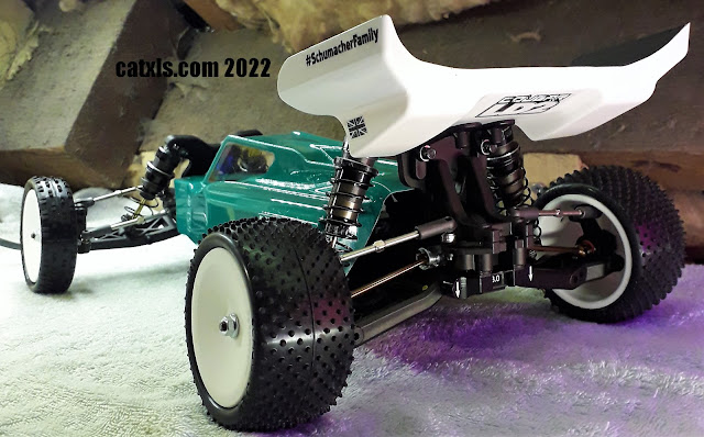
After backing the green paint with white, I let it dry naturally for another couple of hours. After that I removed the window masks and gave it a test fit (above). I am still unsure of the wing, but that can easily be changed.

Another angle of the car.

Time for some well placed decals. As it goes, Schumacher have never (imho) given too many decals in their kits. So you may notice some decals that don't actually belong to this kit.

I didn't use a lot of the kit decals because I'm not so keen on them. I also didn't apply any to the rear wing as I will be repainting it.


You may remember I said, I was unhappy with the wing. I have now completely painted the top surface of the wing matt black and I love it.

I still need to paint the under surface of the wing white but I will have to wait until the black paint fully cures before masking over it.

The car is now slowly becoming the vision I had when starting out. It's not looking too shabby.

Before painting the underwing, I gave that whole side with 1200 grade wet and dry to try and remove the paint layer "steps".

After sanding, believe it or not, I used an automotive white gloss paint. Not only did it cover well, with an excellent glossy finish, it was a lot cheaper than the equivalent Tamiya colour. It's also a 600ml can.

Now all of the painting is complete, I can apply further (but not many) decals.

Considering how many times the underwing was painted, the white paint turned out quite well imho. I am now very happy with the whole colour scheme. I will also be adding a couple of decals on the underside of the wing.

As you can see the wing is not yet properly secured.


Within the not too many decals, there are a couple of nods to the infamous Cat XLS Masami. The Masami decals I chose sat well with the Cougar decals supplied in the kit.

At this point my friends, I will leave the build for now. There are still a couple of things to do on this world championship contending car to complete the build.

So please join me in the final build stages of the Cougar LD2 Stock Spec. Edition buggy

I have made a little paint modification in the above picture. I have simply highlighted the centre fin on the roof of the main body with a matt black covering.

I had intended on doing this modification a little while ago but just didn't find the time.
Above is a little video of the Cougar LD2 moving the steering and rear wheels.
Take care my fellow RC enthusiasts.
25/1/22
catxls.com 2022
Comments